.svg)


When you create a rendering for an architecture project, it’s often helpful for clients and stakeholders to see your building in real-world context.
The challenge with superimposing a rendered building onto an image is making sure the view of the building matches the angle with which the photo was taken. Without doing this, your rendering will look out of place.
To overcome this challenge, you’ll want to use the Camera Match feature in Vectorworks. This blog post will fill you in on everything you need to know about the feature. And if you’re looking for more workflow tutorials, Vectorworks University has you covered with hundreds of helpful courses and videos.

How to Use Camera Match
Step 1 – Prepare the file
Set the view of your model to 3D isometric and place it onto a sheet layer in a viewport.
Import the reference photo and make sure you have a real-world dimension, such as the length of a roof or window. This allows you to correctly scale the image.
Step 2 – Place a reference point
Place a Camera Match reference point. This is simply a 3D object that you place in your model. Do this by clicking the Camera Match tool under the View menu and selecting Place Camera Match Reference. Make sure to select a point you can easily identify in both the photo and your model. You'll be able to rotate the reference object to define the axes in your photo.
Step 3: Import context photo
Navigate to the sheet layer with your isometric view and enter the annotation space by right clicking and selecting Edit Annotations.
Locate your context photo and insert it. It’s recommended to set photo brightness to something like 30% so you’re able to see control lines in a later step. This setting won’t reflect in the final rendering; it’s simply used to make alignment easier.
Step 4: Adjust perspective control lines
Adjust the three sets of perspective control lines, starting with blue (vertical) then red and green. Steps 3 and 4 are demonstrated in the video below.
Step 5: Add dimension & align
Add the dimension you measured in the field to the corresponding control line.
Locate the reference point on the photo that corresponds to the reference point you placed in your model earlier. After placing the target, select Set view to match.
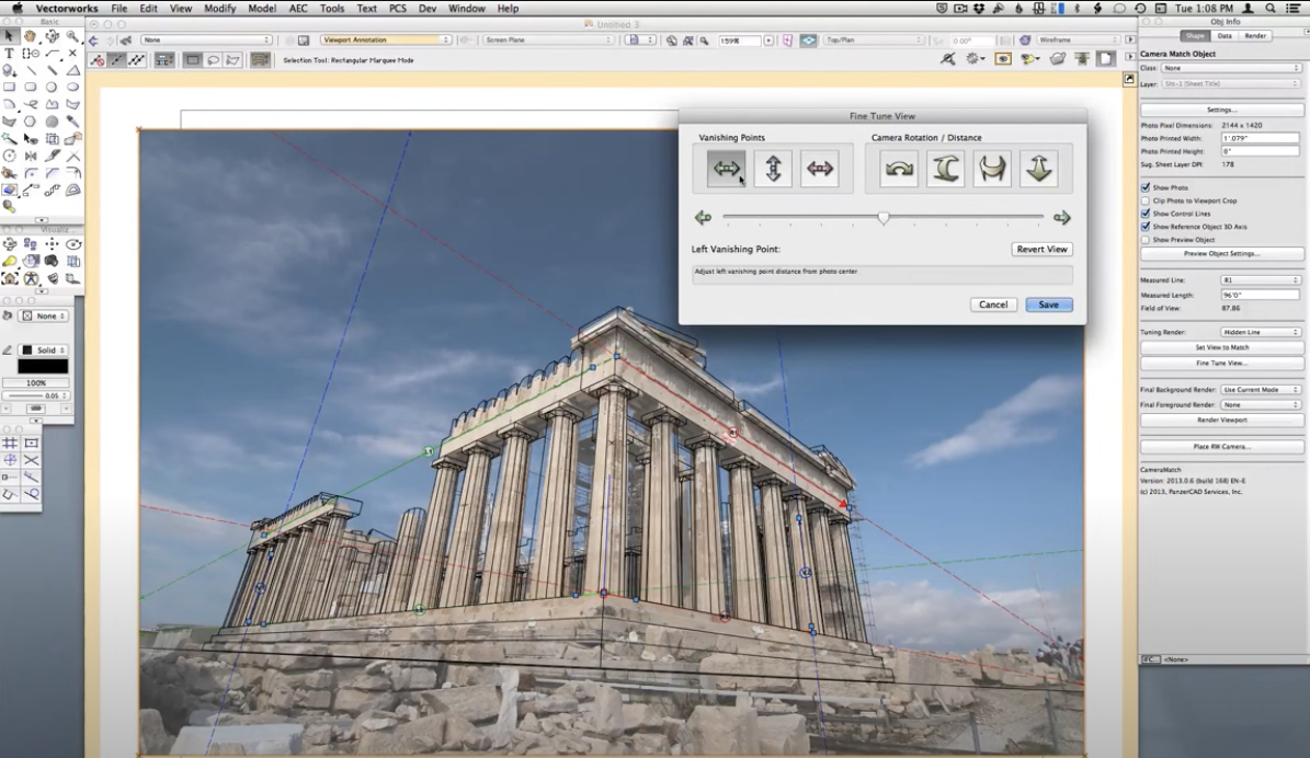
Adjust sliders to fine tune the appearance of the model.
Step 6 – Touchup & render
Render the viewport. Then, jump back into annotation mode for any necessary final touch-ups such as adding a Camera Match Mask, which functions similarly to the Photoshop mask tool. You can see how this works in the following video.
Once you have your model looking how you want it to look, the next step is to render!
Bonus Camera Match Tips
Heliodon – Make sure to use the Heliodon tool to adjust the time of day in your model to the time of day the photo was taken so that you have correct shadows in your model.
Matching difficult views – watch the video below for a demonstration on how to match your model up with a more complicated photo view.
