.svg)


Vectorworks 2024 features limit-defying updates across all of Vectorworks’ design products so you can witness the benefits of a superior workflow.
In this post, you'll learn what's new with ConnectCAD in Vectorworks 2024 and how its streamlined and detailed tools can help you hand over documentation to clients and system contractors.
3D Rack Workflow
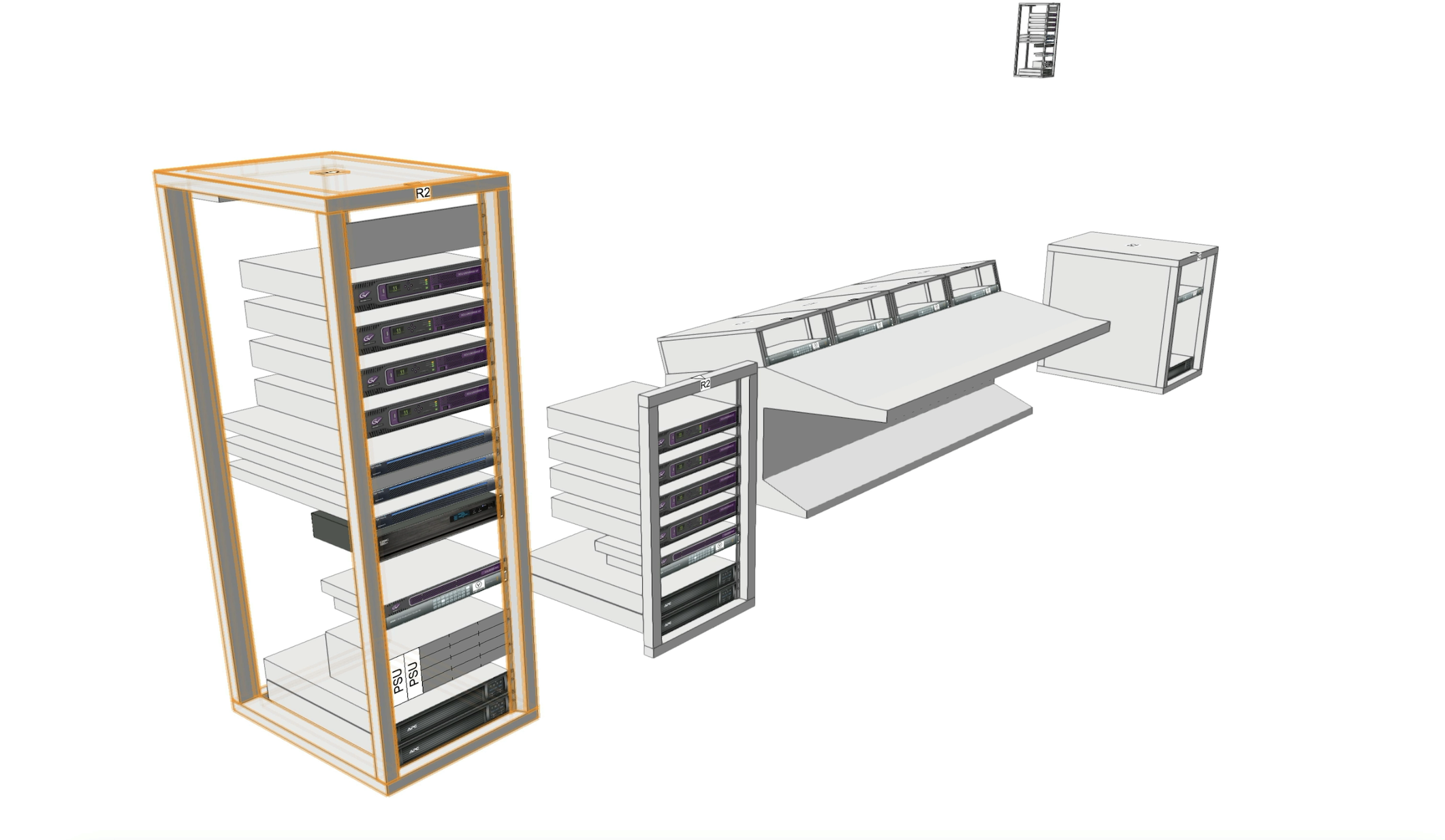
With a new 3D Rack Workflow in Vectorworks 2024, you can easily place equipment into a rack and adjust and move around while maintaining its connection to its schematic device.
The Equipment Rack 3D tool helps you represent a standalone, 3D view of a rack, console rack, or enclosure for a concept drawing or a model view of the design.
You can automatically populate your 3D racks with equipment based on your schematic design using the Create Equipment command or manually add new equipment using the Equipment item tool. When using the command, be sure that the devices on their schematic layer have the correct location information, including Room, Rack, RackU, and — if a modular device — Slot. If you don’t fill in a schematic device’s RackU parameter, the equipment will generate on top of the Rack.
The Equipment Rack 3D tool also allows for a broader range of customization of AV plan's racks, whether it be fourpost, two post, console, or enclosure, and its physical attributes. There are also display items that you can turn on and off, such as doors, power, weight, and a Rack Ruler. This will allow you to recreate and save your most often-used racks for later use.
With new 3D capabilities, your equipment items can be mounted on the front or rear of a rack. To do so, simply change the Mounting dropdown in the Object Info Palette (OIP) from Front to Rear.
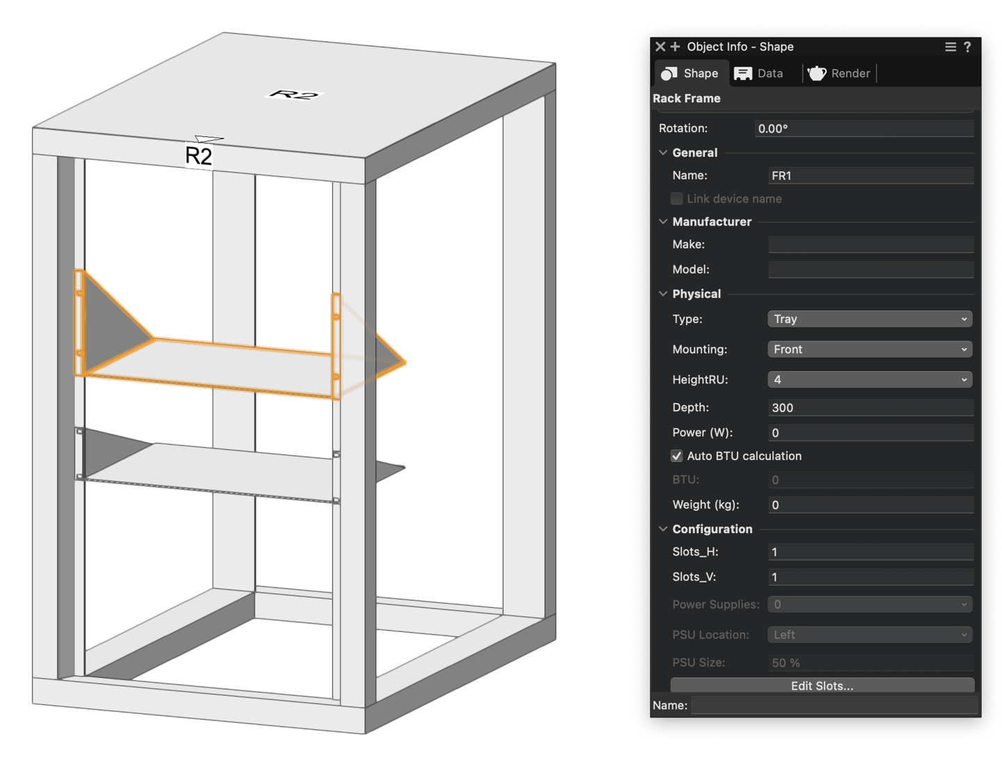
The Rack Frame Tool in Vectorworks 2024 can also help document modular equipment items like distribution amplifiers and SSD Drives in your 3D plan, along with the ability to change the naming on the Slots from the Edits Slots dialog in the OIP. And, if you need a different way to visualize your modular equipment, you can use the tool to change your rack frames to trays. To do this, simply select Tray under the Type dropdown.
Panel Visualization
Panel visualizations in the revamped ConnectCAD allow for better visual representations of the many varied connections that may be a part of your equipment racks.
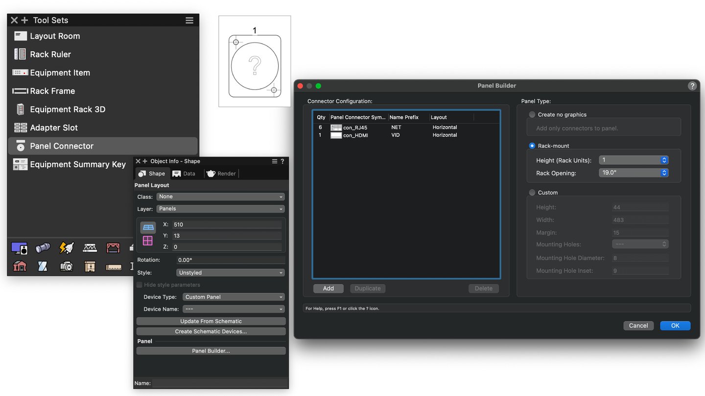
You can now create custom panel layouts with Panel Styles, the Panel Builder and the Panel Connector tool, all of which are located in the ConnectCAD Layout toolset.
These layouts will help you visualize and label standard or custom connector panels with to-scale, detailed views.
The Panel Builder can be accessed in the OIP after placing a connector from the Panel Connector tool. The Panel Builder dialog screen allows you to insert multiple sets of connectors, as well creating a graphical panel representation from default geometry. You can either select a number of default connectors in the Resource Selector or use your own created connectors.
Once the panel is generated, the panel can be edited to add custom graphics and linked text. Then, you can create the associated schematic devices by pressing the Create Schematic Devices button in the OIP and selecting the Schematic Layer as the destination.
You can also easily create custom symbols by duplicating a default connector and adjusting the 2D geometry and attached information.
If your workflow requires you to create a schematic view first, you can use the Create Panel View command. Once you have placed your appropriate jackfield and connector panel devices around your Schematic, you’ll then make them into one panel with the Combine Panels command from the ConnectCAD Drawing menu.
Give that panel of connections a unique device name. This way, you’ll be able to spread multiple connection points across your view that are still associated with a specific panel. Then, use the Create Panel View command to populate a visual representation of those connections.
Rack Elevations & Worksheets
Finally, with the Create Rack Elevation command and Rack Equipment Worksheets, you can easily pull documentation of the needed equipment for built racks and send them off to contractors or equipment purchasers.
The Create Rack Elevation command allows you to generate 2D elevations of your 3D equipment racks. After selecting the command (ConnectCAD > Layout > Create Rack Elevation), a dialog will open in which you can choose your desired sheet layer, naming convention, and whether you want a front and/or rear viewport.
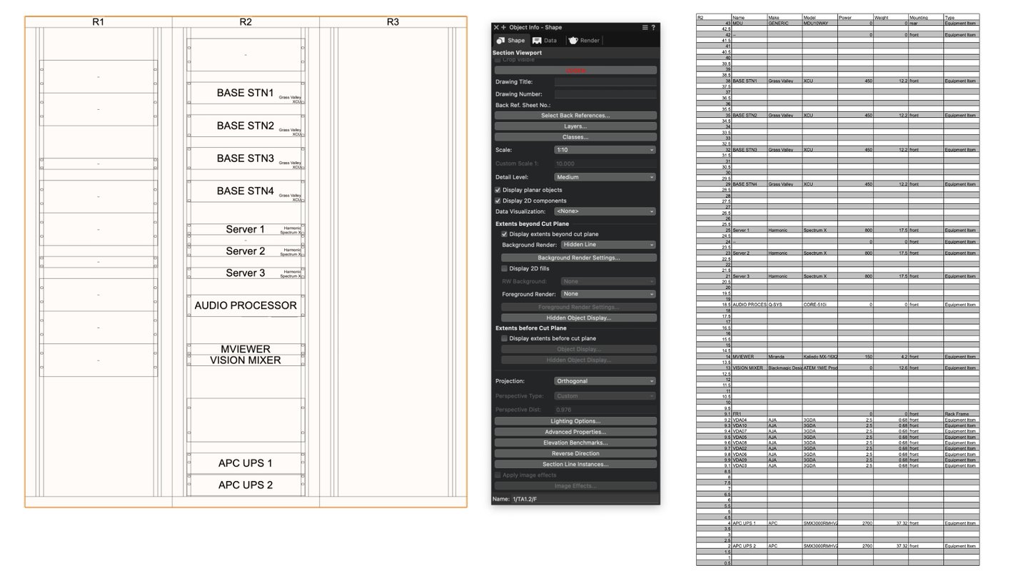
Moreover, the Make Rack Equipment Worksheet tool in the Layout toolset will create worksheets of your populated equipment inside each rack. The dialog gives you the option of reordering and turning on/off various columns associated with the rack.
Learn More About ConnectCAD
For more on the topics covered in this blog post, click the button below:

