.svg)


In our first phase-by-phase overview, you read about predesign. Now it’s time to dig into the second design phase: schematic design.
In this phase you’ll turn your findings from pre-design analysis into spatially accurate conceptual models to share with your clients and consultants.
But first, let’s review what each design phase is all about.
Review | Design Phase Definitions
Predesign
Predesign is what takes place before you get started designing the building. This could include a large variety of things, but common pre-design tasks would be site analysis, zoning/code analysis, building programming, and budgeting. Predesign corresponds to RIBA 0-1 (Strategic Definition and Preparation and Brief).
Schematic Design
Schematic design is about creating the shape and size of the building to-be. As you’re not adding too much detail yet, the schematic design phase is where a lot of collaboration with the client occurs to get all their needs and requirements into drawings and models. Schematic design corresponds to RIBA 2 (Concept Design).
Design Development
Design development involves selecting materials, finishes, products, and providing specificity into the concepts laid out in schematic design. This phase often involves collaboration with consultants like engineers and landscape architects. Design development corresponds to RIBA 3 (Developed Design).
Construction Documents
Regarded as the phase that accounts for the largest percentage of the architect’s work, construction documents are where you produce the technical drawings needed to both gather approval from municipalities as well as to construct the building. Construction documentation corresponds to RIBA 4 (Technical Design).
Schematic Design with Vectorworks Architect
The strength of Vectorworks Architect for schematic design can be broken down into five major pillars:
- Flexible modeling to explore unique and bespoke design solutions
- Smart tools you can put to work to respond to the building program and project requirements
- The ability to use templates and styles to coordinate drawing sets before drawings are even created
- The ability to incrementally add detail and make quick revisions that reflect across documentation as the project progresses
- Full graphic control for presentations
Let’s get into it.
Exploring Design Solutions with 3D Modeling
3D modeling is useful for schematic design because it allows you to create prototypes of your ideas quickly and easily. This helps you communicate ideas to the client, and to make sure that everyone is on the same page before moving forward with the project.
When thinking about your modeling tool, flexibility is key. If you started with a massing model, you want to be able to quickly modify the box-like shape into geometry with more architectural form. You also want to be able to quickly test several form solutions to identify the best one for the project program. The ability to quickly iterate in this way makes Vectorworks Architect the ideal tool for exploring ideas.
Responding to Project Program & Requirements
If you read the blog about predesign, you’re familiar with the Space object already.
It’s often helpful to lay out a project in two dimensions before creating a three-dimensional model. Spaces give you the best of both worlds — simply draw space objects to create separate rooms or areas, then use the Create Walls from Spaces command to generate a 3D model. This is a great way to experiment with different layouts and see how the space will actually look in this early stage of the project.
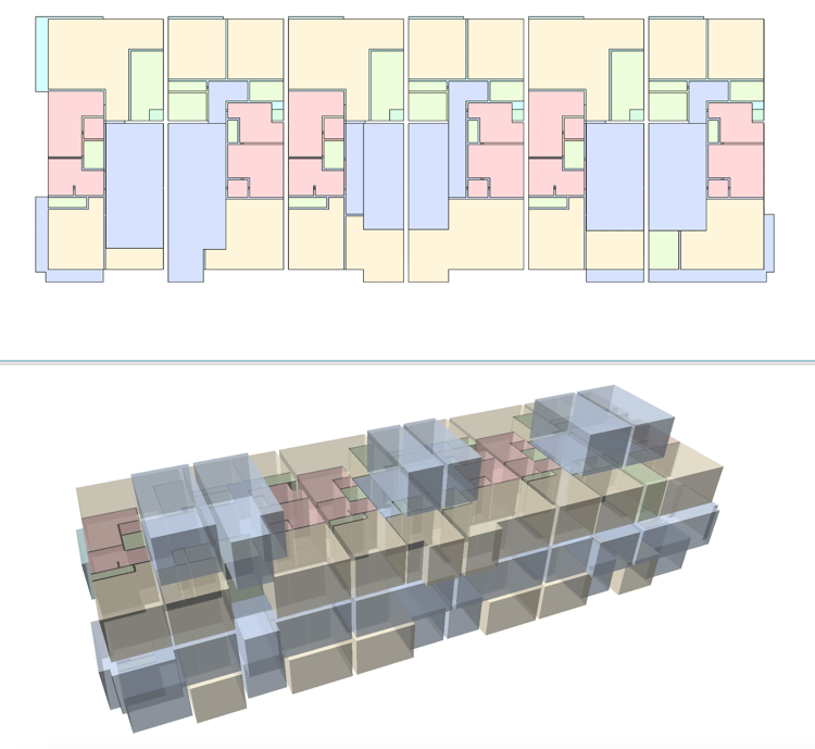
Here's our sample "High Tor Townhomes" project laid out with Spaces.
Sound cool? It is — Spaces give you helpful data like area and volume, so as you’re exploring layouts, you can easily determine whether your ideas meet project requirements. It’s also possible to use average cost-per-area numbers to create a rough estimate on if your concept fits within the budget. It’s not 100% accurate but being in the ballpark helps determine if you should move forward with a concept.
Incrementally Add Detail with Flexible Tools That Remain Useful for the Entire Project
The tools you use in Vectorworks are built with the end goal in mind. You can use the wall tool to create a very simple, conceptual wall and rest assured that this wall is ready to have detail added incrementally as the project progresses.
Here’s the benefit: when it’s time to add detail during design development, you can add information to the wall itself, or swap it out for a more detailed wall type that already exists in your resource library. So, your schematic models serve a greater purpose throughout the remainder of the design process. They aren’t locked into their initial form upon creation.
You NEED to be using object styles
Take advantage of object styles to insert uniform geometric elements across the file without the need to model or define them every time.
Many architects like to store object styles for walls, windows, and doors, allowing them to quickly insert these objects into the design file. As we’ve said before, object styles are essentially templates for objects you know you’ll use consistently — make sure to use them to save tons of time!
Here’s how you might use styles:
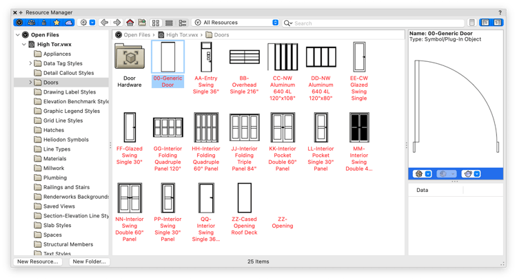
Say you’re working on a small residential dwelling and are creating a conceptual model with Spaces. You know you want each room to have a window. You can go into the Resource Manager and select a basic window style, then place that window style into the desired locations. For all intents and purposes, this basic window is not what you’d submit for construction documents later — instead, during design development, you’d either edit the window style to add configurations, which would apply to all instances of that style, or replace individual instances with a new style. No need to configure each one individually.
The same idea applies to walls and doors. You can insert a conceptual style then add components and detail to the style later in the project.
Vectorworks 2023 introduced direct modeling of doors and windows in 3D. If you use a window style that has its width and height set to By Instance, then you can draw windows directly on a façade in 3D to quickly explore different design concepts.
For many object styles, some parameters are locked by the style and must be the same for every instance, while others can be set individually for each instance. Some object styles can optionally be based on a manufacturer’s catalog item, which will lock certain parameters. All this makes for a flexible and powerful tool that allows for complete control and customization of your model.
Take Full Control of Graphics
You need to impress clients. Plain and simple. That’s why you need to be able to maximize the graphical experience of your presentations.
High-Quality Rendering Options
A built-in rendering engine allows you to give graphical form to your models. Connections to leading rendering platforms like Twinmotion, Enscape, and Lumion are also available if you’re looking to go a little further with the rendering.
Automatic Drawing Creation
Let technology take care of the tedious work for you! Creating drawings can certainly feel laborious if you’re doing it manually, so Vectorworks has some practical ways to automate the creation of drawings from the 3D model.
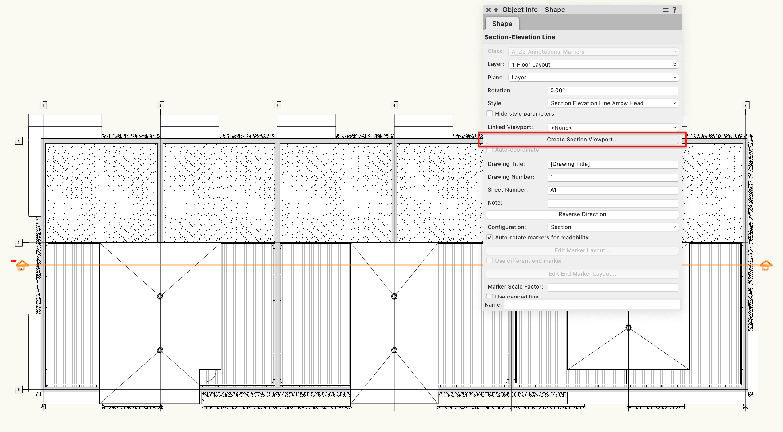
Look at the Section-Elevation Line tool as an example.
Located in the Dims/Notes toolset, this tool can be used to create a reference line from which quick section and elevation viewports can be generated. These lines are coordinated with the viewport, so if you need to adjust, you can — the markers will automatically update with the correct information.
 Simply draw a Section-Elevation Line with the tool, then select "Create Section Viewport" from the Object Info palette.
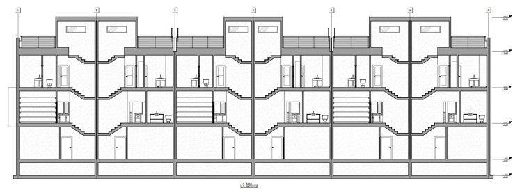
Easy as that! The Section-Elevation Line in Image 1 created this section in about 10 seconds.
The real upshot is that these reference lines can be a part of your file template and placed before you even have a model. It’s quite a productive workflow to be able to set up all your viewports at the start of a project, then be able to quickly navigate to them and update them as you model and add more detail.
The Section-Elevation Line is one of many “Smart Marker” tools in Vectorworks. Others include the Reference Marker, Interior Elevation Marker, Detail Marker, and Drawing Label tools. Each of these tools can link to viewports to reduce errors when producing documentation sets.
Here’s another method to automatically create drawings or presentation viewports. This method uses the Clip Cube tool.
→ RELATED: Underrated Vectorworks Features | Clip Cube
The Clip Cube tool surrounds your model or part of your model with a transparent box whose six faces you can drag to “clip” away parts of the model momentarily. With a more focused view on screen, you can simply righty click on the clipping face and select “Create Section Viewport” to generate a section. Be sure to read the article linked above for more information on using the Clip Cube!
Up Next: Design Development!
Check out our exploration of the next design phase by clicking the button below.

